
 Capacity multi-touch is the predominate form of human interaction with portable devices nowadays. This ranges from there mobile phone, tablet, laptop and even watches. Multi-touch are also used in numerous applications outside of portable computing, such as point-of-sale (POS) terminals, interactive signage, and industrial consoles. This multi-part tutorial will take an in-depth look at how multi-touch is implemented.
Part 1 presents an overview of the theory of operation behind many commercially available multi-touch systems. Part 2 discusses some of the filtering and multi-touch detection techniques. Part 3 presents some commonly implemented multi-touch gesture recognition algorithms. Finally, Part 4 discuss how multi-touch drivers are typically implemented. Part 1 is this article. The other three parts will be published sequentially. Please check back periodically, or click the Follow button at the bottom of this article to receive notification when next part in the series becomes available.
Multi-Touch Screen Construction
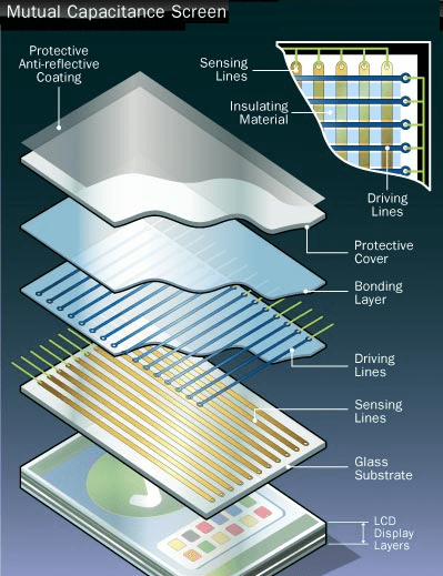
Figure 1: Multi-touch screen construction.
Capacitive multi-touch screen is generally made of multiple layers, commonly referred to as the “stack”. The stack is placed above the LCD display, starting with an insulating glass etched with the sensing lines. Similarly, a layer of dielectric material etched with the driving lines place on top, with the dielectric material between the driving lines and the sensing lines. Finally, a bonding layer and a protective layer are added to complete the stack.
The sensing lines and the driving lines are made of nearly transparent conductive material called Indium Tin Oxide (ITO). They are oriented in a X-Y pattern to form multiple junctions. For example, a 20 x 12 array, there would be 240 junctions. A mutual capacitance is formed at each junction between the sensing line below it, and the driving line above it. This capacitance is measured when the driving line is energized.
Capacitive array with such arrangement is known as having a “cross-bar” pattern. Other patterns are possible, such as the diamond pattern and patented patterns such this and this. What makes a good pattern is symmetry, and low stray flux line. Some patterns can be laid out on a single layer, simplifying the stack construction, therefore reduces the cost. More recent development integrates the capacitive sensor in or on the LCD, known as in-cell or on-cell sensors. These types of sensors further reduce, or even eliminate the stack layers; but due to the proximity of the sensors to the LCD, noise immunity becomes a greater challenge. One way to achieve noise immunity is to scan the sensor during the LCD frame sync, or blanking period; but this also means the scans have to be very fast.
Self- and Mutual-Capacitance
Figure 2: Self- and mutual-capacitance.
There are two types of capacitance at each junction: self capacitance and mutual capacitance, as is illustrated in Figure 2. Self-capacitance is the capacitance from the driving lines to ground. It is often used to detect presence of a touch; but since the receiving line is not involved, self-capacitance is less suitable for determining where the touch is, especially when multiple touches are present. In contrast, mutual–capacitance is between the driving line and the sensing line; therefore it is much more suitable for detecting where the touches are. Note that self-capacitance diverts electric field away from mutual capacitance, which leads to less charge accumulated on mutual capacitance.
Extracting Self- and Mutual-Capacitance
Extracting self- and mutual-capacitance from an array requires an understanding of the equivalent circuit model. Figure 3 show the equivalent circuit model in an array. Let’s focus on the capacitance at the junction j and k, where j is the row, or drive line index; and k is the column, or sensing line index. At junction (j, k) there is a mutual capacitance, Cm[j][k] between row[j] and col[k]. There is also a lumped self-capacitance for row[j], denoted as Csrow[j][k]. Similarly, there is a lumped self-capacitance for col[k], denoted by Cscol[j][k].
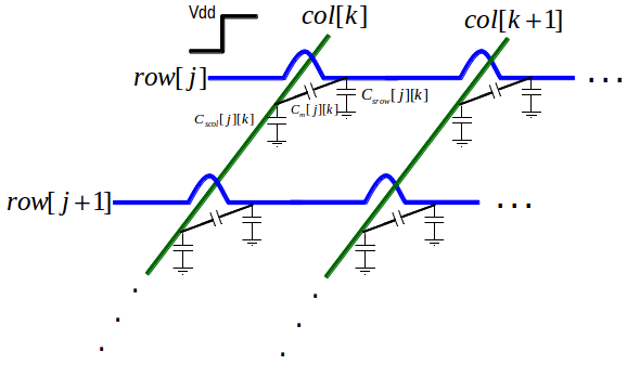
Figure 3: capacitive sensing array circuit model.
Each junction can be boiled down a simple circuit shown in Figure 4. The capacitor on the left and the right are the lumped self-capacitance of row and column, respectively. The capacitor in series is the mutual capacitance.
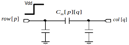
Figure 4: simple equivalent circuit of a junction.
The extraction of self- and mutual capacitance is done generally in two ways. One way is to treat the capacitance as impedances by driving the row with AC excitation of known frequency and amplitude, and then monitoring the amplitude and phase caused by the impedance through the sensing line. This technique require a more complex driving electronics and bandpass filter. A second way, known as “charge shuttling”, measures the charge accumulated on the capacitor by driving the capacitor with a simple digital driver, and then transfer the charges to a charge amplifier for measurement.
Both methods require some coordinated switching of the terminals of the circuit circuit terminals to isolate capacitors for sampling. While the exact implementation may be different, the operating principles are basically the same. Figure 5 shows how the terminal can be manipulated to measure charges across each capacitor.
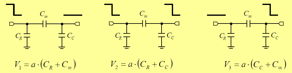
Figure 5: Isolating capacitance for measurement.
In the Figure 5 example, the first phase is to drive the row and ground the column. From that, V1 can be measured. The second phase is to drive both row and column and measure V2. Driving both row and column together excludes the effect of the mutual capacitor. The third and last phase is to ground the row and drive the column and get V3. It is not hard to see that, after three phases, we will have three linear equations to solve for three unknowns. The coefficient, a, is a constant closely tied to the charge integration time. Usually the algorithms that process the touch map only require that the measured values are linearly proportional to the capacitance.
Summary
This article is Part 1 of a series of article presenting an overview of the capacitive multi-touch technology. This article focused on the theory of operation, stack construction and sampling techniques resulting in a touch map. The next article will focus on the algorithms that process the touch map to extract touch information.
Further Reading
(The above article is solely the expressed opinion of the author and does not necessarily reflect the position of his current and past employers)