
 This is Part 2 of a 4-part series on multi-touch technology. Part 1 presented the theory of operation behind many capacitive multi-touch sensors. This article will present the common filtering techniques and touch detection algorithms.
Managing Noise
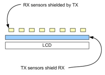
Figure 1: Driving lines (TX) shielding the Sensing lines (RX) during readout.
Capacitive multi-touch sensors operate in a rather noisy environment. First, the sensor stack sits on top of the LCD display, which emits noise, especially the back-light. There are several ways to manage the display noise, such as adding a clear layer of ITO between the display; or putting the driver layer beneath the sensing layer, as during charge readout, the driving lines are held to supply or ground, effectively shield the sensing lines. Display noise tends to manifest as isolated spikes randomly occurring across the touch panel; a spatial filter would do a good job at eliminating the noise. Another method is to use horizontal or vertical sync from the display subsystem to gate the panel scan; however, these sync signals are not always present or easily accessible.

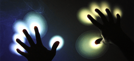
Figure 2: Touch closes the circuit with charger.
Second, during charging, the noise from the PWM switched converters, both AC/DC and DC/DC, can creep into the sensing lines when the user touches the screen, because a touch closes the circuit through the human body to the common ground–a form of common-mode noise. Charger noise is a difficult noise to deal with, because it often has high-amplitude harmonics that change with load. The changing harmonics comes from the fact that the AC/DC converter adjusts to different loads by varying the PWM signal going to the current switches.

Figure 3: Charger noise profile is load dependent.
If improperly handled, charge noise can render a touch screen completely useless. Figure 4 shows a criss-cross touch patterns for different chargers. It is clear that good charger design goes a long way in reducing the effect of charger noise. However, in portable devices, chargers are often interchangeable, making it impractical for users to stay with a specific charger model; some mitigation has come from the touch controller.

Figure 4: Criss-cross touch patterns for different chargers.
Filtering charger noise can be achieved with a combination of anti-alias filter and high panel scan rate. Without anti-alias filter, low panel scan rate (low f) will repeat the charger noise harmonics every f/2 in the frequency spectrum, increasing the chance of the noise bands creeping into the signal band (< 20Hz) . Higher panel scan rate will help separate the alias more, but is quickly limited by computational resource to process the touch map.
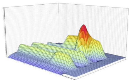
Figure 4: Charger noise manifests as raised columns.
If charger noise is unaddressed, it can manifest itself as raised columns in row-first panel scans, as is shown in Figure 4. Often the amplitude can exceed the threshold used to detect touches. For this reason, many touch controllers on the market today implement more sophisticated dynamic thresholds, or apply morphology filters to detect parabolic shapes generated by real touches.
Lastly, devices such as induction cook tops and LED lights can emit EMI strong enough to impact touch sensing. Normally, EMI from external sources can be mitigated with shielding. On portable devices like a smart phone, this is done by enclosing the phone with conductive cover. Some place a metallic plate in the back of the phone case; others construct the phone with metallic casing altogether. This way, when the phone is held, the user grounds the case, providing a path for the EMI energy to dissipate. But if the phone is placed on a table insulated from the earth ground, the EMI has to be dealt with another way. Similarly the internal flex ribbons need to be shielded and placed with trace running orthogonally to other nearby ribbon cables to minimize cross-coupling.
Given that EMI and charger noise are both common-mode noise, a great way to eliminate the noise is to apply differential sampling, so that the noise is eliminated at the source.
Extracting Touches
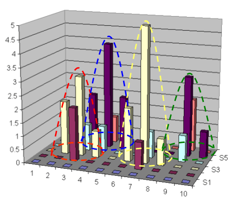
Figure 5: Parabolic interpolation.
After filtering, a 2D array of mutual capacitance measurements is ready for touch extraction. The simplest way would be using peak detection. In this scheme, the touch map is scanned, and then N highest peaks are remembered. But the node X-Y location are row and column indices, a rather coarse number. To achieve touch coordinates at the display resolution, interpolation using the peak and its neighbouring values must be used. There are several interpolation techniques, with the parabolic interpolation being one of the more popular one. Parabolic interpolation technique assumes a touch will result in a Gaussian-like function that can be efficiently approximated by an inverted parabola. By fitting a parabola about the peak’s neighbouring points along the X- and then the Y-axis, the parabola’s maxima location can be calculated. This gives a touch location at the display resolution.
Besides the location, there are other useful properties can be extracted a touch. For example, the touch area may hint the touch pressure and finger size. The touch area can be estimated by solving for X-axis intersection of the inverted parabola, but by running clustering algorithms, such as the density based clustering algorithm or the patented use of watershed algorithm in multi-touch. Given that most touches have elliptical shapes, the Principle Component Analysis (PCA) can be applied to a cluster to extract the orientation. Touch orientation can be used to twist a graphical knob with just one finger, or for game control. For example, the Apple track pad reports both orientations as well as positions.
Even with all the filters, small noise can still get through that will lead to small but visible “jitters” on the touch screen. Small jitters can be removed by applying a first-order filter of the form:
X_new = (1-a) * X_old + a * X_in
where the coefficient, a, is a linear function of the speed of the touch. This adaptive formulation provides stronger filtering when the finger is stationary, and agile tracking when the finger is moving.
Summary
This article is Part 2 of a series of articles presenting an overview of the capacitive multi-touch technology. This article focused on the noise sources and filtering techniques, as well as touch extraction algorithms. Part 3, the next article, which will focus on gesture recognition.
Further Reading:
- Cypress Charger Noise Article
- Display Noise on Touch Screen
- Shape filter for multi-touch
- DBSCAN clustering algorithm
- Touch interpolation techniques
- Jitter filter for multi-touch
(The above article is solely the expressed opinion of the author and does not necessarily reflect the position of his current and past employers)