
With 3D cameras such the Microsoft Kinect and the Creative Gesture Camera readily available, it is now possible to create some neat applications, such as reconstructing a live scene in 3D, detecting hand and body gestures, and helping robot navigate. In this article I will share some of my own experiences in working with 3D cameras.
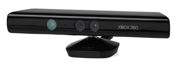
Figure 1(a): Microsoft Kinect 360

Figure 1(b): Creative Gesture Camera
How the Microsoft Kinect Works
The first generation Microsoft Kinect is based on patented structured light technology developed by PrimeSense. The general speculation is that the Kinect emits a fixed speckle pattern that allows range to be determined. Given that Kinect has two RGB cameras, it may be possible that stereo vision concept is used, where each speckle on the target will show up as a pixel in each of the two RGB cameras, and the pixel position of the speckle in each camera define a line of possible location of the target in space. But since there are two cameras, there will be two intersecting lines, and the point of intersection determines the 3D location of the speckle, and therefore the target.
How the Creative Gesture Camera Works

Figure 2: 3D-TOF camera operating principle (from wikipedia.org).
The Creative Gesture Camera works based on the 3D Time-of-Flight (3D-TOF) principle by shining near IR light on the subject and then measure the phase difference between the transmitted light and the reflected light. The transmitted light is modulated by G1 at frequency 


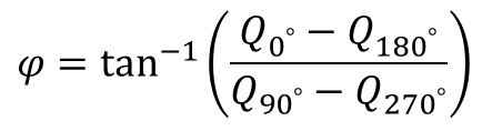 where the four


3D Rendering using OpenFrameworks
Both of these cameras produce depth maps much like the standard RGB cameras, except that, at each pixel, a depth value is returned instead of a color. The depth map can be rendered in 3D to show the vertices (aka point cloud). With meshing, a solid can be constructed from the point cloud. Figure 3 shows an example of point cloud collected by 3D cameras and its solid rendering after meshing.

Figure 3: Vertices and solid rendering of point cloud data from a 3D camera.
To render the point cloud data, I used the OpenFrameworks (OF), a powerful open-source, cross-platform run-time framework that enables rapid application development. It integrates several powerful software packages under one roof, with clearly defined, intuitively named APIs. OF is supported on Windows, Linux, OS X and Android. As such, applications written with OF are generally portable across OS platforms. OF already has add-on for Microsoft Kinect, called ofxKinect; and the Intel Perceptual Computing SDK (PCSDK) has OF support for the Creative Gesture Camera. In another article, I described how to use OF to create anaglyph (stereo) viewing of the 3D scene.
Creating Mesh
To create meaningful surfaces or solid from point clouds, I used ofMesh and ofVboMesh class in OF extensively. The main difference between the two is that ofVboMesh has noticeable performance advantage because it stores the vertices in the GPU memory. A mesh is formed of many triangles, each defined three vertices plus a normal vector, a total of 12 data elements. Given three vertices, a, b and c, the vertices and the normal can be added to the mesh this way:
[code language=”cpp”]
void addSurface(ofMesh &mesh, ofVec3f &a, ofVec3f &b, ofVec3f &c)
{
ofVec3f norm = ((b-a).crossed(c-a)).normalized();
mesh.addVertex(a);
mesh.addVertex(b);
mesh.addVertex(c);
mesh.addNormal(norm);
}
[/code]
With these 12 data elements, OpenGL knows how to draw the surface and compute any proper virtual lighting and texture mapping. A chapter on OpenFrameworks 3D subsystem is available on the web, and serves as an excellent tutorial.
Now that we know how to draw triangles using OF, how do we choose which group of three vertices should form a triangle? Luckily, creating triangles is relatively straightforward for structured point clouds, but significantly more complex for unstructured ones. Depth maps gathered from the 3D cameras are typical of structured point clouds; that is, the pixels have predefined spatial arrangement, i.e., row and column, and its coordinates are defined by 


PXCUPipeline_ProjectImageToRealWorld() API to convert depth map to vertices map. With the vertices map, one can traverse the map to form triangular strips.
In contrast, the vertices in unstructured point cloud do not have definitive spatial relationship. To reconstruct 3D surfaces from these points, these points must first be re-sampled based on their spatial distribution, such as the Poisson-Disk Sampling, then surfaces are formed using method such as the Marching Cube. Fortunately, these advanced algorithms are readily available in Point Cloud Library (PCL), an open source library. To download and configure PCL, check out my article on how to configure and run Kinect and PCL for Windows 8.
Gesture Recognition
3D cameras also facilitate gesture recognition. One of the first problem that gesture recognition has to solve is figure-ground separation. For instance, to recognize hand gesture, one must first separate the hand image from the background image. The depth data allows one to separate the foreground from the background by using the depth data. Once the hand image is isolated in a bounding rectangle, well-known image processing techniques, such as finding blob for locating the palm, contour for isolating the hand, and convex defects for identifying the fingers. Luckily, the Intel PCSDK supports gesture recognition, making finger and palm position detection simple.
Below is a video of how I used the Intel PCSDK, along with the the OF ofSoundPlayer class to create a gesture-controlled car dash audio player with map. The implementation detail of this project will be the subject of a different article.
If you enjoyed this article, I’d love to hear from you.
(The above article is solely the expressed opinion of the author and does not necessarily reflect the position of his current and past employers)